Internal hydrants are made on the basis of harmonized European standards, which strictly define their technical parameters, hydraulic properties, colors, symbols, markings and instructions, as well as a detailed scope of tests of constancy of performance. Each type of hydrant may be in trade if it has a certificate issued by notified bodies in the EU.
The Minister of the Interior has also specified the conditions that these hydrants must meet, especially in terms of flow rate (efficiency), minimum and maximum supply pressure, inspections and maintenance.
The lowest supply pressure on the hydrant valve must not be less than 0.2 MPa and the flow rate at this pressure must not be less than:
- Internal hydrant with semi-rigid hose DN25 – 60 l / min.
- Internal hydrant with semi-rigid hose DN33 – 90 l / min.
- Internal hydrant with folded hose DN52 – 150 l / min.
- Hydrant valve 52 – 150 l / min.
The maximum supply pressure on the hydrant valve must not be greater than:
- Hydrant with semi-rigid hose DN25 – 1.2 MPa
- Hydrant with semi-rigid hose DN33 – 0.7 MPa
- Hydrant with a flat hose DN52 – 0.7 MPa
- Hydrant valve 52 – 0.7 MPa
The above hydrants and valves in the facilities are very often together and also together with other fire protection systems e.g. sprinklers. Considering that the hydrants are supplied from the general water supply network or from their own pump stations, it is very difficult to meet all the requirements set in the Ordinance of the Minister of the Interior. It is even more difficult to meet these requirements in high-rise office buildings with their own pumping station and where all types of internal hydrants need to be installed: DN33 hydrants in garages, DN25 hydrant in offices and DN52 in industrial rooms.
In this situation, we are forced to build separate supply networks and divide them: not one pumping station, but a few placed in the zones: basement, 5th floor, 8th floor, etc. In addition, there are other fire protection installations in these facilities where pressure is higher than allowed in hydrants, e.g. 1.4 MPa.
Solution to this problem are internal hydrants and valve cabinets with constant flow that can work in installations with a supply pressure up to 2.5 MPa.
These hydrants have a pressure control and regulation device and enable maintaining a constant flow regardless of the hydrant supply pressure. It should be remembered that this pressure cannot be lower than 0.2 MPa.
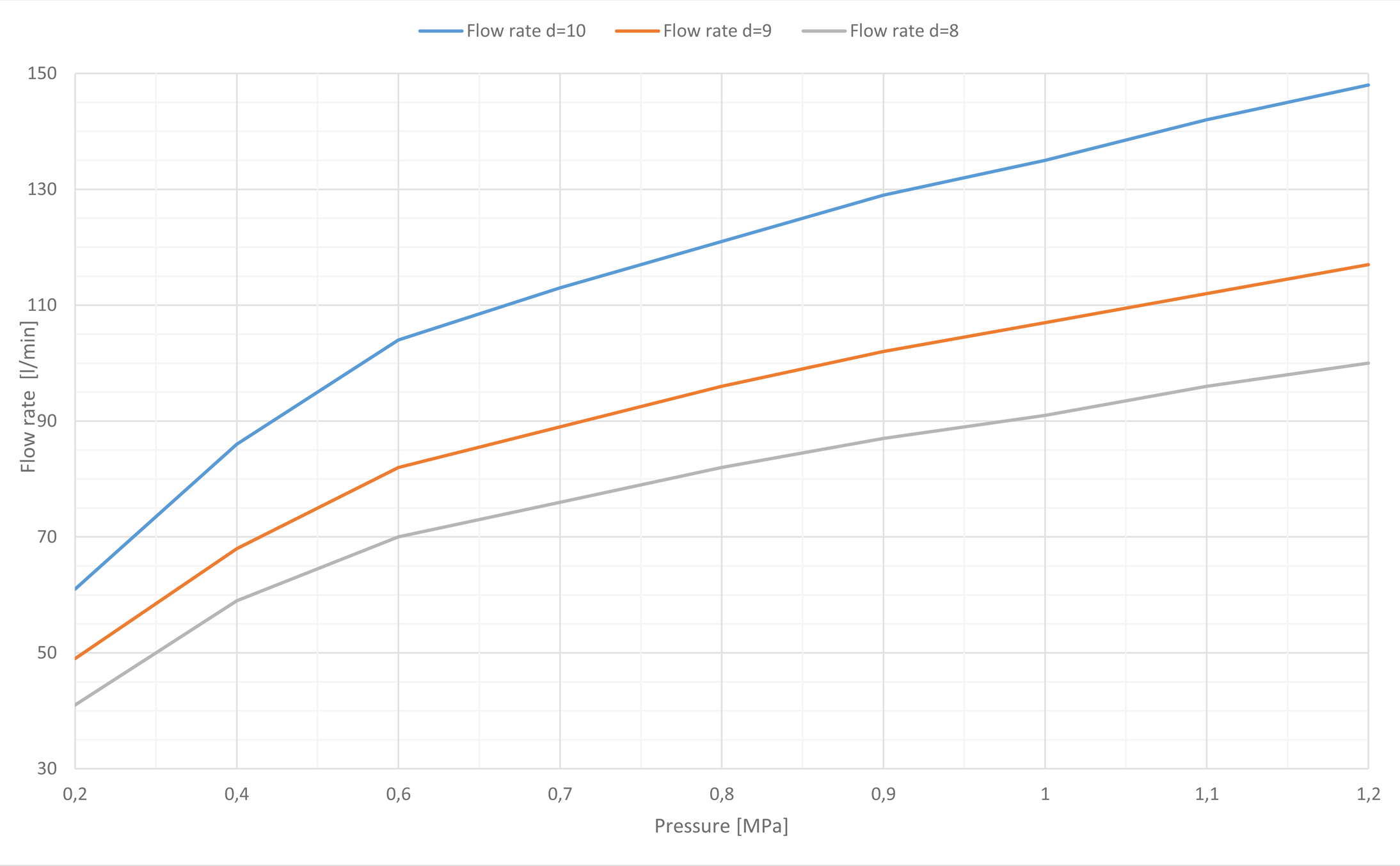
In these hydrants, the measured static pressure is equal to the dynamic pressure, which allows to determine the hydrant’s efficiency knowing its characteristics (Figure 1). The static pressure is shown on the manometer and allows continuous monitoring of the internal hydrant’s readiness for operation. Thanks to the applied technical solutions, compact dimensions, ease of use and maintenance, these hydrants facilitate the design, construction and supervision of the fire protection installation in the facility and directly contribute to the reduction of investment costs.
Hydrants have been tested by CNBOP-PIB. The test results confirm the constant flow of the hydrant, which is unaffected by the change of the supply pressure.